

Kitfox Model 7 SS Pre-cover Checklist
This post includes the precover checklist for the Kitfox 7SS
It was requested of me to post my precover checklist. Below is a link to a poorly scanned pdf and photos are also below.


Transponder Antenna Mount Plate
Kitfox mounts their transponder antennas in the back of the plane but they don’t provide you with the hardware or information to do it yourself. I have made my own drawings.

The photo John McBean sent of the Kitfox 7 transponder mount plate.
Kitfox has been mounting their transponder antennas in the back of the plane recently. This is because the new ADS-B functions cause interference with the communications system. The fuselage does not have an antenna mounting plate in the back of the plane so one has to be fabricated. Apparently, Kitfox will begin selling the plate but there is no clarity on when that plate will be available. Unfortunately this is not something I want to wait on Kitfox for because it must be done before covering.
The Factory sent me a photo of the plate but not dimensions or directions. I did some measuring and came up with dimensions included here. My plate fits just right. I had the machinist make it for me on a break. I was originally going to use 1/16” 6061-T6 aluminum stock but the machinist only had the thicker material in stock. It worked out great!
WARNING! DO NOT DRILL AND RIVET THE PLATE INTO THE FUSELAGE! ONLY DRILL THE PLATE INTO THE STRINGER!
The stringer is not a structural piece of metal but the fuselage tubing is. If you drill holes in the fuselage tubing, it will weaken the structure.

Transponder mount plate side view.

Tansponder mount plate bottom view.

Transponder mount plate angle close up.

Transponder mount plate other side view.

Tow Transport Kit
The Kitfox 7 STi has the an option for a tow transport kit. The kit is great but the instructions are horrible. Here is what the factory sent me.

The Tow Transport Kit is an option that includes equipment for trailering or towing your plane with the wings folded. The instructions in the manual aren’t very helpful so I have uploaded the instructions that the factory sent me.

Telescoping Bar Instructions
The kit includes a fabric pad for the rudder and 4 braces for the wings. I think that it is a great option but the instructions are just bad. The color copy of the manual helps.

Dual Pin Door Latch
Instructions for the Dual Pin Door Latch. You probably don’t want to buy it!
Kitfox offers a dual pin door latch for their doors but there isn’t actually much information about them. Even the instructions are not in the manual. I have attached the pdf instructions here for reference.
What is the Dual Pin Door Latch? Its a system designed for an aerobatic Kitfox that keeps the doors from popping open in flight. The dual pins are more secure than the standard latch, but they are also more complicated and are much heavier.
I bought the option thinking that it would allow me to crack the doors open in flight to improve airflow through the cabin. As it turns out, the dual pin doors can’t be cracked open in flight. Kitfox was nice enough to let me return the latch in exchange for the standard latch.
Thank you Kitfox!

The latch is very secure but also complicated.

Getting the Plane on Wheels
Normally gear don’t go on this early in the build because they must be removed to cover and paint. Additionally, the aircraft typically needs to be level to set up the wings. I’ve decided to put them on for a few reasons.
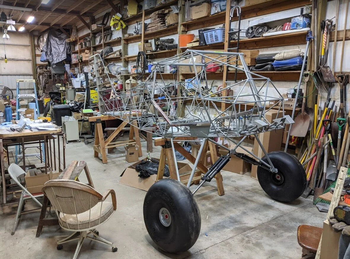
The gear and wheels are almost installed!
Normally gear don’t go on this early in the build because they must be removed to cover and paint. Additionally, the aircraft typically needs to be level to set up the wings. I’ve decided to put them on for a few reasons. First, I wont have to level the plane to put my wings on because my wings are already built and rigged for me. Second, I want the plane to be movable and the gear make a great rolling sawhorse.

Kitfox Shock Monster 2.0 viewed from the tail.
We started the process by putting the wheels in the tires which was not easy. The wheels have to be squeezed into place and the provided bolts are not long enough to do the trick. We used a much longer bolt to do the initial compression of the whee and tightened it down until we could thread the actual bolts on. At first, it seemed like the tire was not seated correctly, but after adding a little air, they filled in nicely. As we added pressure the wheels almost doubled in size!
The install of the gear was pretty straight forward. We of course had to do some reaming of all the bolt holes and we sanded off substantial powder coat. We first got the mount plates and cabane V installed. Then we attached the main gear legs. Instructions for this step were completely omitted from the manual but it was easy enough to assemble. Then we attached the Shock Monster Gear. The provided bolts for the gear were larger than the provided holes so we actually had to re-drill the holes to accommodate the larger size. We then installed axles and brake calipers. And finally the wheels went on.

The T-3 Tailwheel installed!
The next step was the tail wheel. I got the T-3 tail spring. The whole assembly pretty much just bolts right on after some light reaming. It took a bit of finagling to get the bolts through and tightened. The instructions were also lacking for this step because the factory only provides guidance for the standard tail wheel.

Finally we took the plane off the sawhorses and stood her up on her own 3 feet! The suspension didn’t sag at all because it is designed for the full weight of a finished aircraft so the plane sits higher than it will when it is finished.
We finished the day off by installing master cylinders for the breaks and shaping the foam on the ends of the elevator, horizontal stab, and rudder.

Back to The Machinist!
I struggled for hours trying to get more bad hardware to fit. I should have known better. The rudder pedal bearings are now flawless after their trip to the Machine Shop!

From the factory, the Kitfox rudder pedal hardware is unusable. The machinist made quick work of them!
Yesterday we spent about 4 hours working on rudder pedal bearings. (This is after we spent about a half day sanding the rudder torque tube) As expected, none of the black nylatron bearings fit in the rudder pedals. Part of the issue was bad powder coat job on the inside of the pedal assembly that resulted in corrosion. We spent about an hour fixing that.
The manual says to “file the bearings to fit”, whatever that means? Instead we attempted to reduce the outer diameter of the bearings using the factory recommended method: chucking the bearings in a drill and sanding them down as the drill turns. This method I find incredibly primitive and inaccurate. The method is basically a jerryrigged lathe with a hand drill and sand paper. But since these bearings were for the rudder pedals, and the rudder pedals don’t really rotate that much, I decided to give the method a try. After about 4 painful hours sanding, all the bearings had an acceptable fit.
As if the 4 hours wasn’t enough, I practically had to hammer the bolts in even after reaming, only to find that the bolts were not even remotely straight. As a result, the plastic bearings no longer fit. What a waste of time! We closed up the shop on a bad note.
The next morning, the whole rudder pedal assembly was in the machine shop. A couple hours later, as expected, the hardware came out as a perfect fit! Machinist’s notes:
So, the ½ Nylatron bushings needed both the OD reduced and the ID enlarged in order to get the proper fit.
Turns out the bolts not being straight were only part of the problem. The hole was not centered throughout the entire length.
When a part like this must be drilled from each end, it is important that both are centered precisely.
It is not uncommon for a drill to drift off center in a long hole, but when not centered well from the start, there is no chance things will meet properly in the middle. So, the bent bolts magnified this problem.
Had to remove 0.007 - .010” off the OD of the other bushings.
Took longer than I anticipated, but things are done.
He not only had to STRAIGHTEN MY BOLTS for me, but he also had to effectively re-manufacture the bearings. How is an average kit-builder supposed to handle these issues? As you may be able to tell, I am pretty frustrated with the kit. My faithful building assistant had an interesting quote today. He said, “ this kit is full of dog work.” I get that these kits require some above and beyond work, but they are effectively asking you to own your own machine shop.
For those of you out there building, I hope you are able to find a patient and talented machinist nearby. For those of you thinking about building, find a machinist nearby before you start!

Milling down Elevator Bearings and Bushings
A machinist should be doing precision machine work, not a home builder. The Kitfox rudder hardware needed professional help.
Today we continued work on the flight controls. I spent a few hours this morning fitting washers and bolts so that my controls are buttery smooth. The progress is almost invisibly slow, tomorrow we will do a video update to get everyone on board.
We also, by a stroke of fate, found a machinist in town who very professionally fit my elevator bearings and bushings. The factory recommends that you sand the bearings down in a drill press:

Many builders spend countless hours sanding. I got it done in 40 minutes.
According to the Machinist:
“The inner steel sleeve diameter was:
OD —-8mm (minus) { ~0.314”}
ID ——4.5mm { ~0.177 inch}
( Bolt is 3/16” or 0.187” )
The Brass Bushing:
OD —— 7/16“
ID ——- 5/16” minus { ~0.311” }
In order to make things work, I increased the bore in the steel sleeve to accept the 3/16 Hex Headed bolt. Then Bored out each Brass Bushing to the correct assembled fit for the 8mm sleeve. In my opinion, inch & metric parts for this particular assembly got mixed up. “

The finished product.
The finished product turned out to be flawless. It should have come from the factory this way. I imagine that this won’t be the last time I see this issue. I will do some before and after photos to show the improvements.
First Actual Build Step - Horizontal Stabilizer
Here are some notes on what to do when you start building your Kitfox horizontal stabilizer.
The first build step in the manual is to put together the horizontal stabilizer so I figured I’d start there. The process involves reaming holes, shaping the wooden ribs, and then bonding those ribs into place.
Some things I wish I knew before I started:
Grind the end the holes on the leading edge of the tail are incredibly hard to get to grind the end of your reamer so that it can fit into a socket. Then use a universal joint to allow for a drill to be used to drill a hole. This would have saved me hours and this trick comes up again frequently.
Get at least spring clams pony clamps to hold ribs in place and two 2 ft scrap pieces of 2x4 to prop up the horizontal stab portion.
Try to avoid grinding the leading edge of the ribs to get them to fit. Just grind the trailing edge.
Use a syringe to apply the Hysol, and make nice filleted corners.
Clean up sloppy Hysol applications with denatured alcohol before you let it dry.
Keep a close eye on the stiffeners as they may fall over or lean.

Open Manual and Inventory
The first think I did when I arrived with the kit is open the manual and start reading. I then began inventory, but decided that I can inventory most of the items as I go.

The first think I did when I arrived with the kit open the manual and start reading. I then began inventory, but decided that I can inventory most of the items as I go.

The Delivery
The Kitfox STi is loaded and shipped from Idaho to montana

John McBean’s Kitfox equipped with the 135hp+ Rotax 915is.
My kit was supposed to arrive in March but COVID-19 prevented the delivery. I decided to serve as my own postman and pick the kit up myself in Homedale, Idaho.
The journey began a 17 hr drive from Northern California to Western Montana which was where I would be building the kit. It is a beautiful drive through Eastern OR and WA.

Mt. Shasta with some clouds.
I then picked up a 16 foot Penske Box Truck and drove 8hrs to Homedale, ID to pick up the kit from the factory.

Kitfox kit packed very nicely in the back of the box truck.